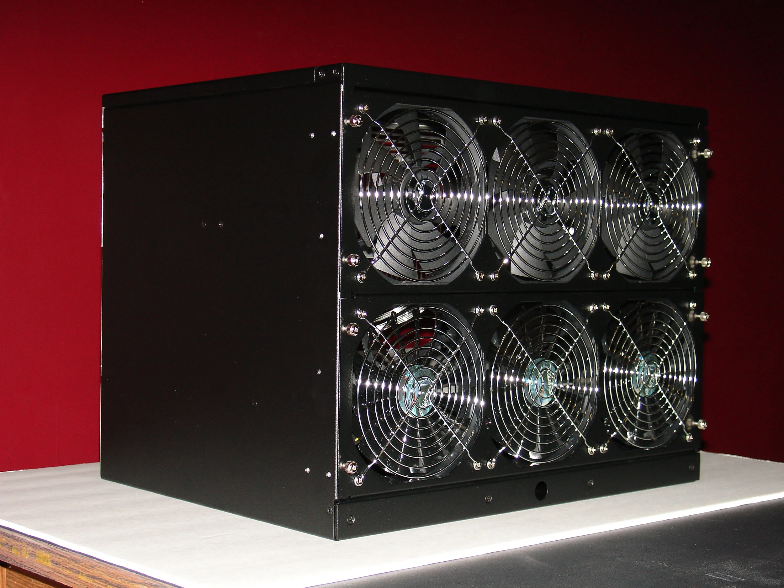
The Prototype Arrives
The GS Cube arrives with all major components assembled.
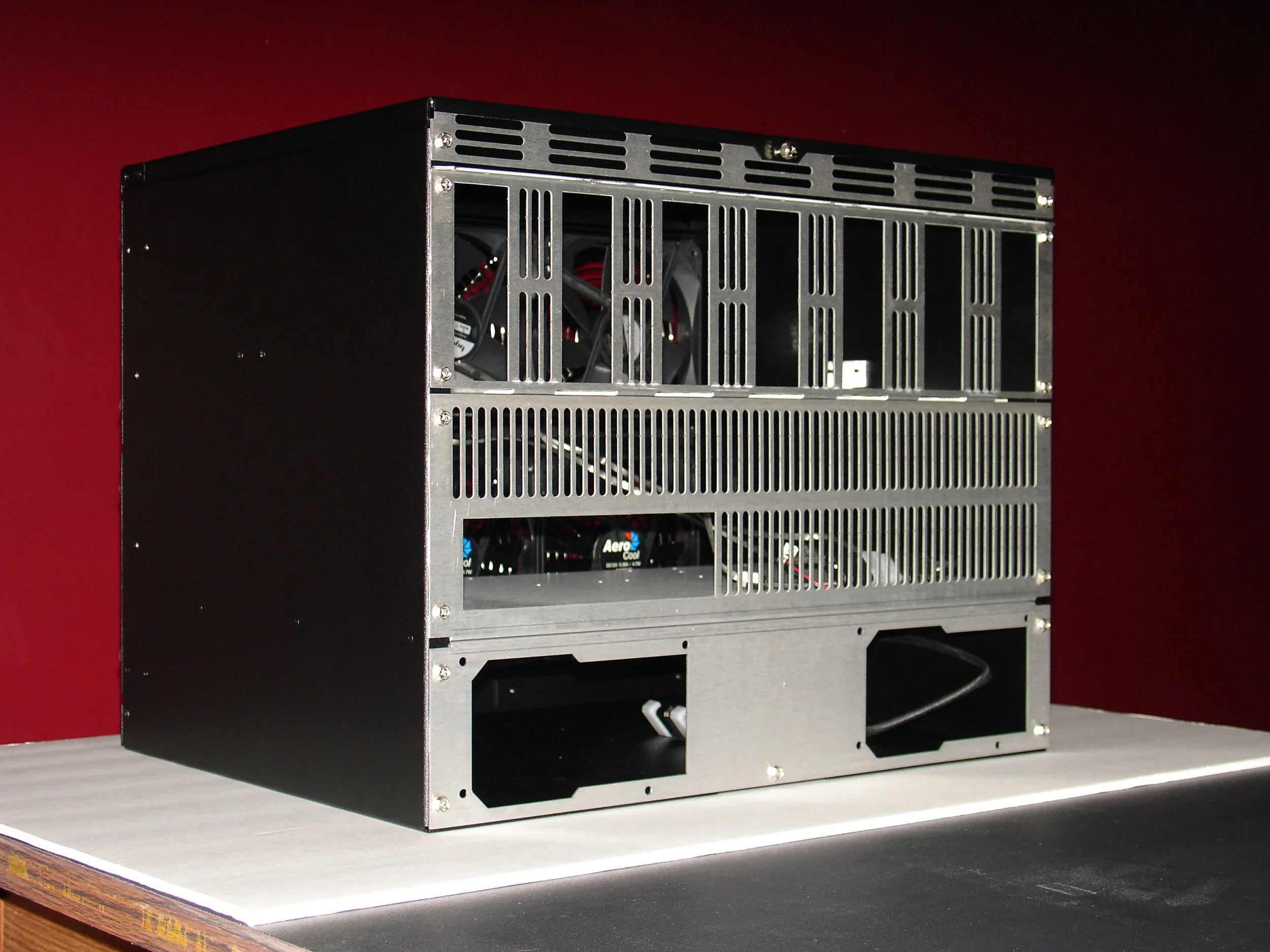
The Back of the GS Cube
Hot air exits on this side of the system. The top, thin GPU lock-in panel and the motherboard panel are removed during assembly. This is indicated by the use of thumb screws in the production version.
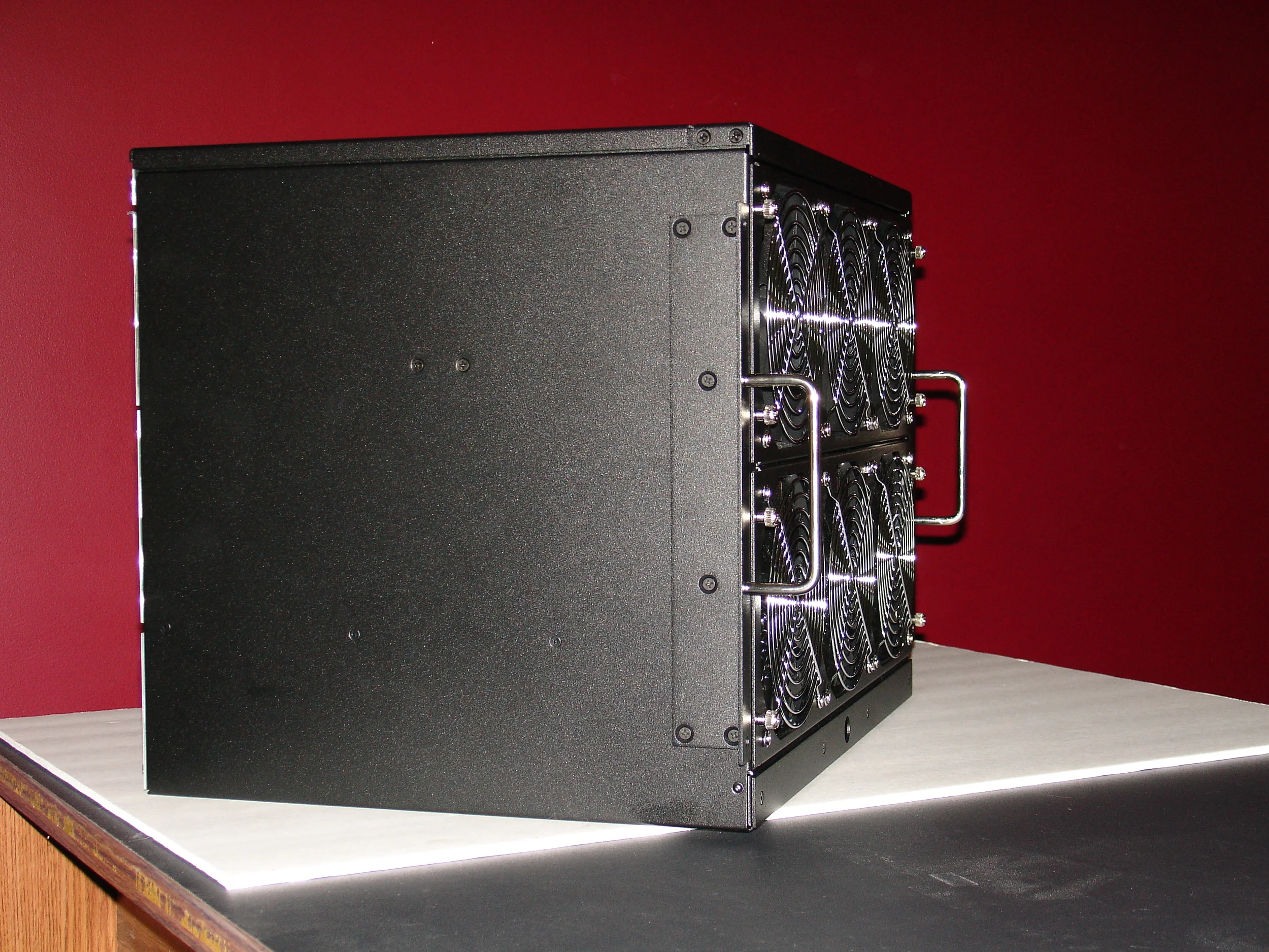
Optional Rack Ears
Rack ears are optional, but they add a nice touch and are essential for rack mounting.

Removing the Top Fan Tray
The top and bottom fan trays are removed to allow full unobstructed access during the build.
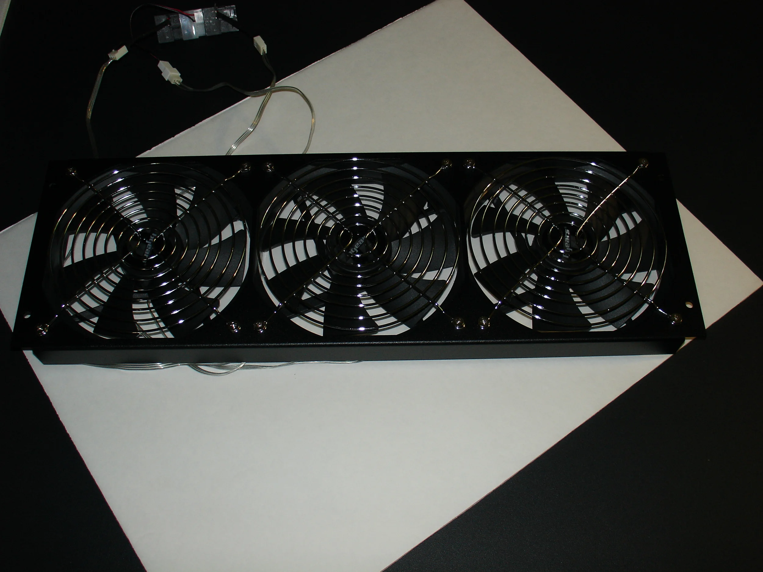
Top Fan Tray

Bottom Fan Tray Removed
The top and bottom fan trays are removed to allow full unobstructed access during the build. The motherboard tray and card support are now visible.

Top and Bottom Fan Trays
All fan trays are interchangeble.
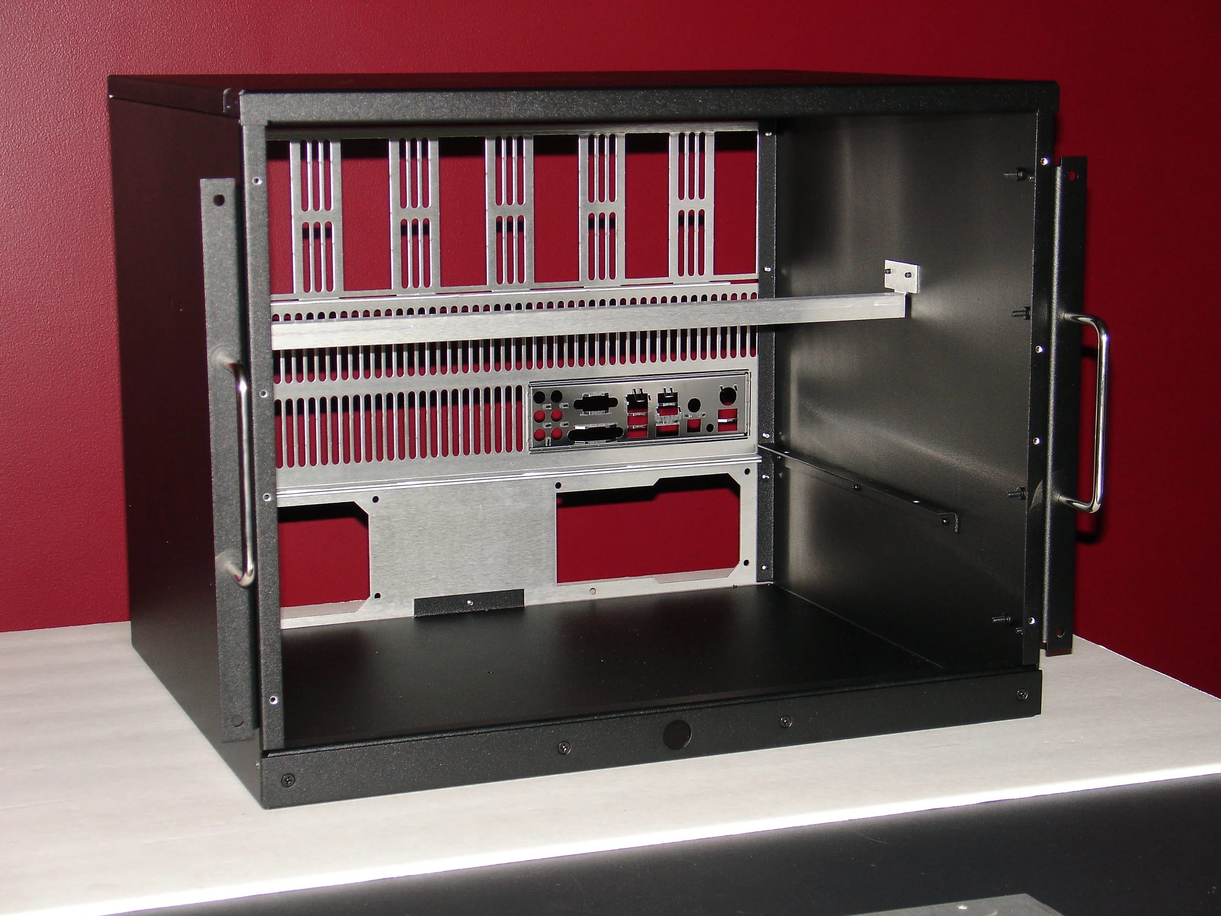
Motherboard Tray Removed
The motherboard tray is removed to enable the easy installation of the motherboard and optional hard drives.
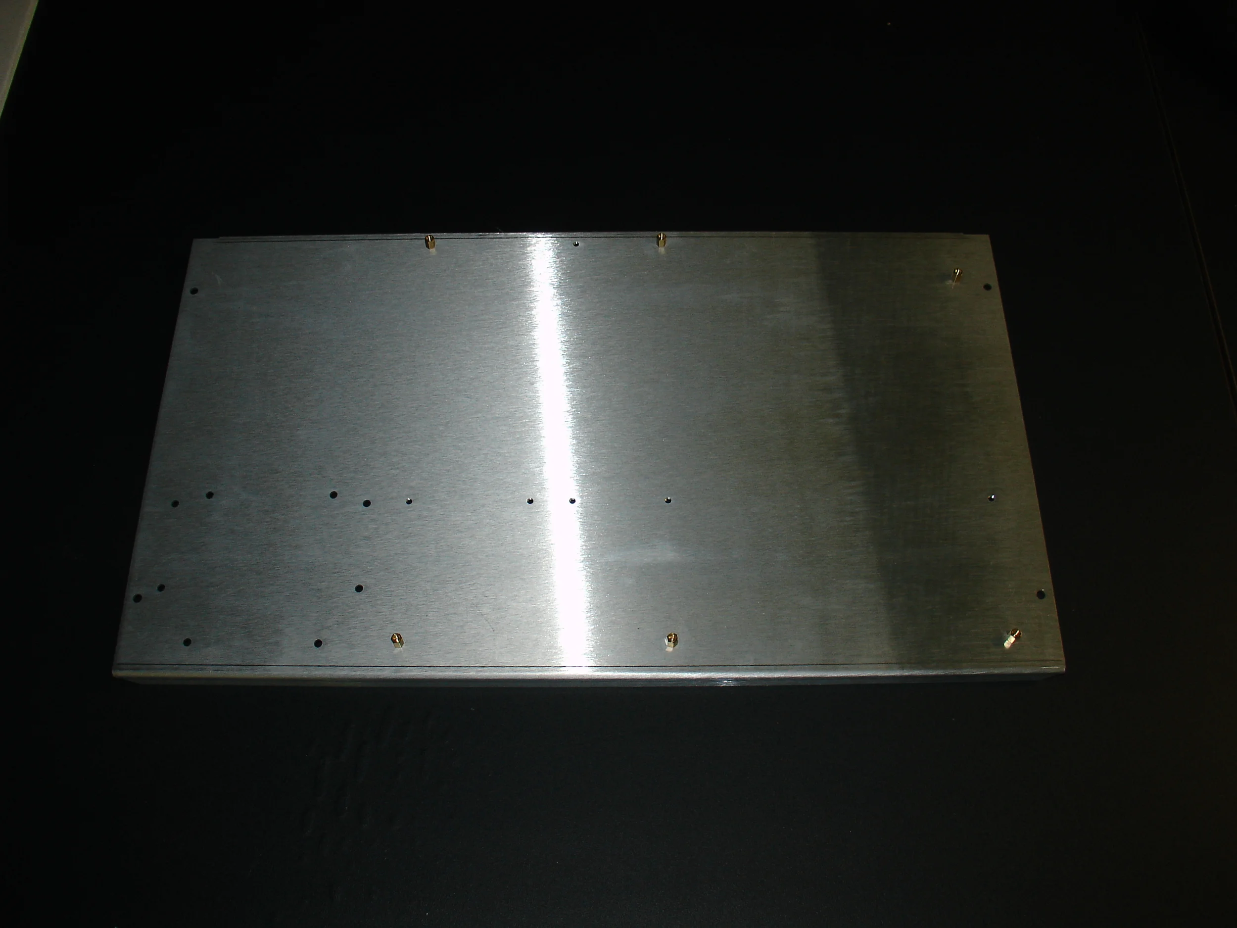
Motherboard Tray
The motherboard tray supports all standard motherboard form factors. Risers are supplied but not installed to reduce rework.

ATX Motherboard on Motherboard Tray
The easiest way to determine the pattern your motherboard requires is to place your motherboard on the motherboard tray. Marking the tray with a sharpie through the motherboard mounting holes makes this step go very quickly.
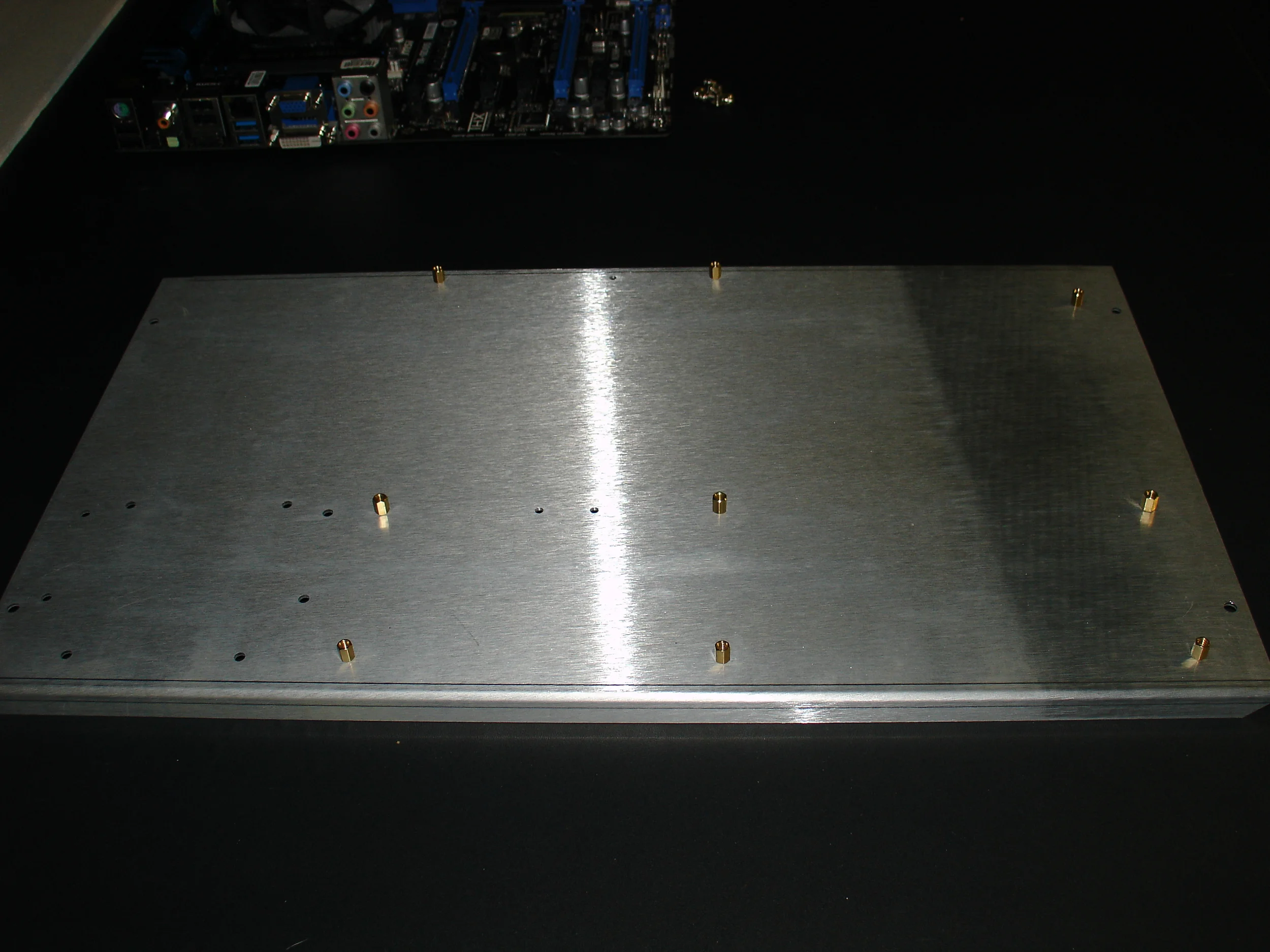
Motherboard Tray with ATX Standoff/Riser Pattern
Finger tighten the motherboard standoffs/risers and then place a 1/4 turn on them using pliers.

Optional Hard Drive Mounting
Once the motherboard standoffs/risers are installed, flip the motherboard tray over and install your hard drive directly onto the motherboard tray (upper left corner of the picture). Both 3.5" and 2.5" drives are supported. If larger motherboards are used the hard drives can be mounted below the tray (if they clear your power supplies) or on the bottom of the chassis itself.

Hard Drive Mounting Closeup
Mounting holes are provided for 3.5" and 2.5" drive sizes.

Mounted Hard Drive and ATX Motherboard
The motherboard tray is designed to accommodate and ATX motherboard and one 2.5" or 3.5" hard drive. The lower level of the chassis can hold additional hard drives if required.

Motherboard Tray Insertion
The fully assembled motherboard tray is easily inserted from the front of the chassis at an angle. The right hand side is lifted into place and the entire motherboard tray is rested on the motherboard supports.

Installed Motherboard Tray
The right hand side of the motherboard was lifted into place and the entire motherboard tray was rested on the motherboard supports. The tray is then slid to the back of the chassis.
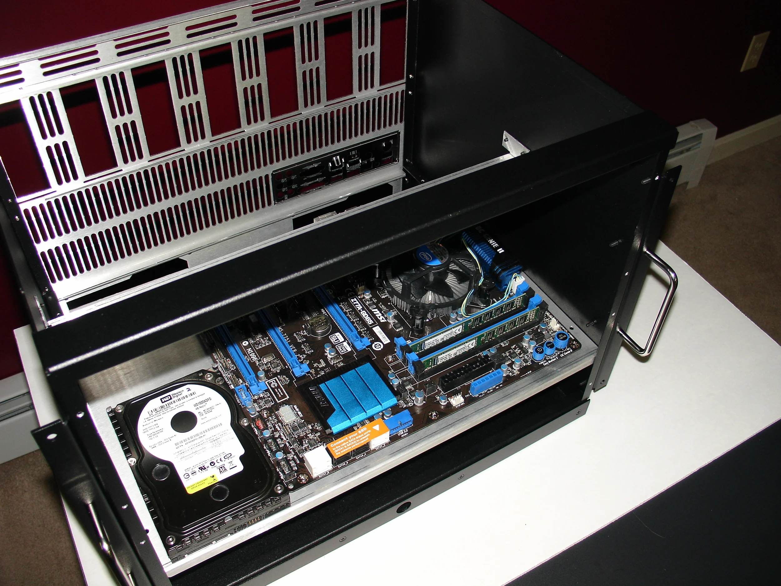
Motherboard Tray at Front of Chassis
The motherboard tray is slid from the front of the chassis to the back.

Motherboard Tray at Back of Chassis
The motherboard tray is slid from the front of the chassis to the back.
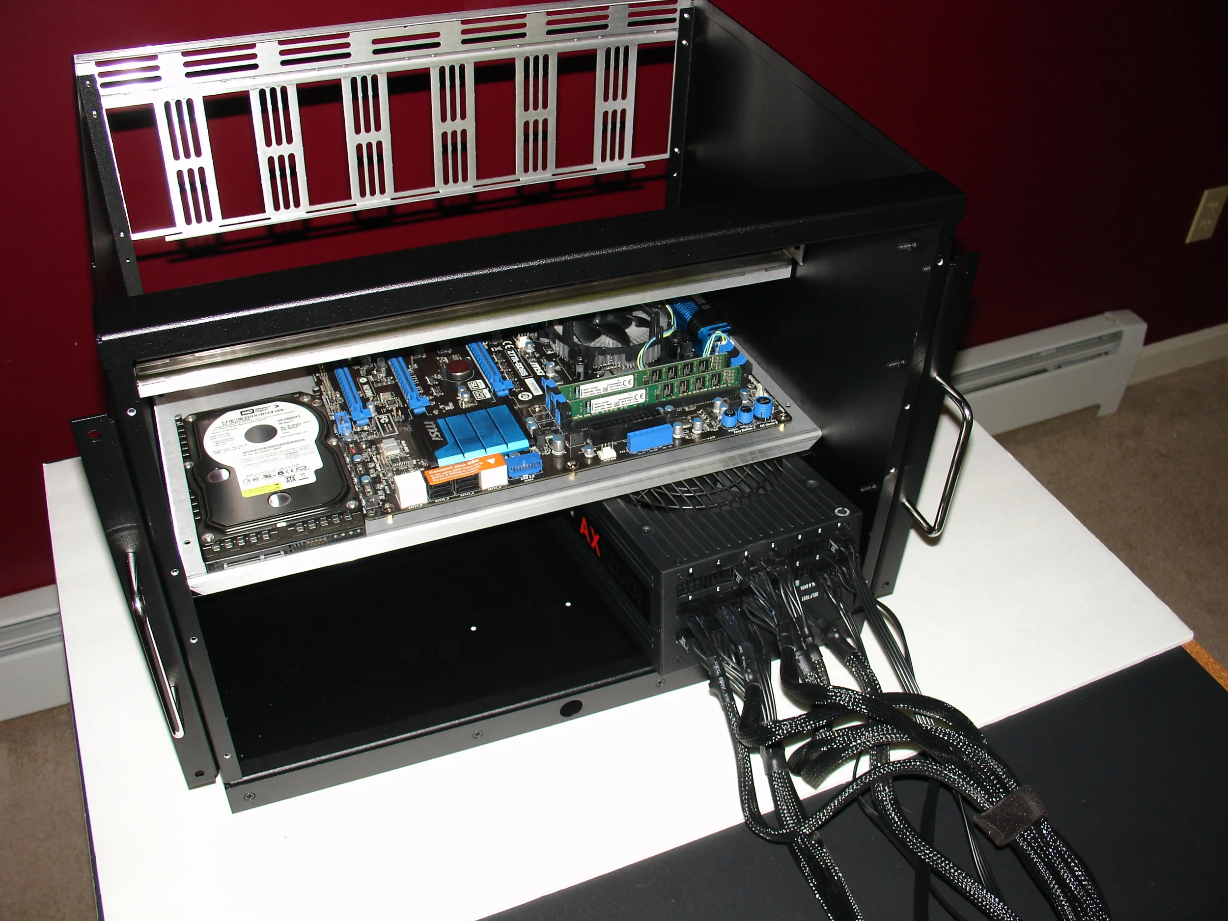
First ATX Power Supply Installation
The motherboard tray has been slid to the back of the chassis but has not been attached. The allows the first power supply to be slid in from the front at an angle. Connecting all required power supply cables before power supply installation makes wiring easier.
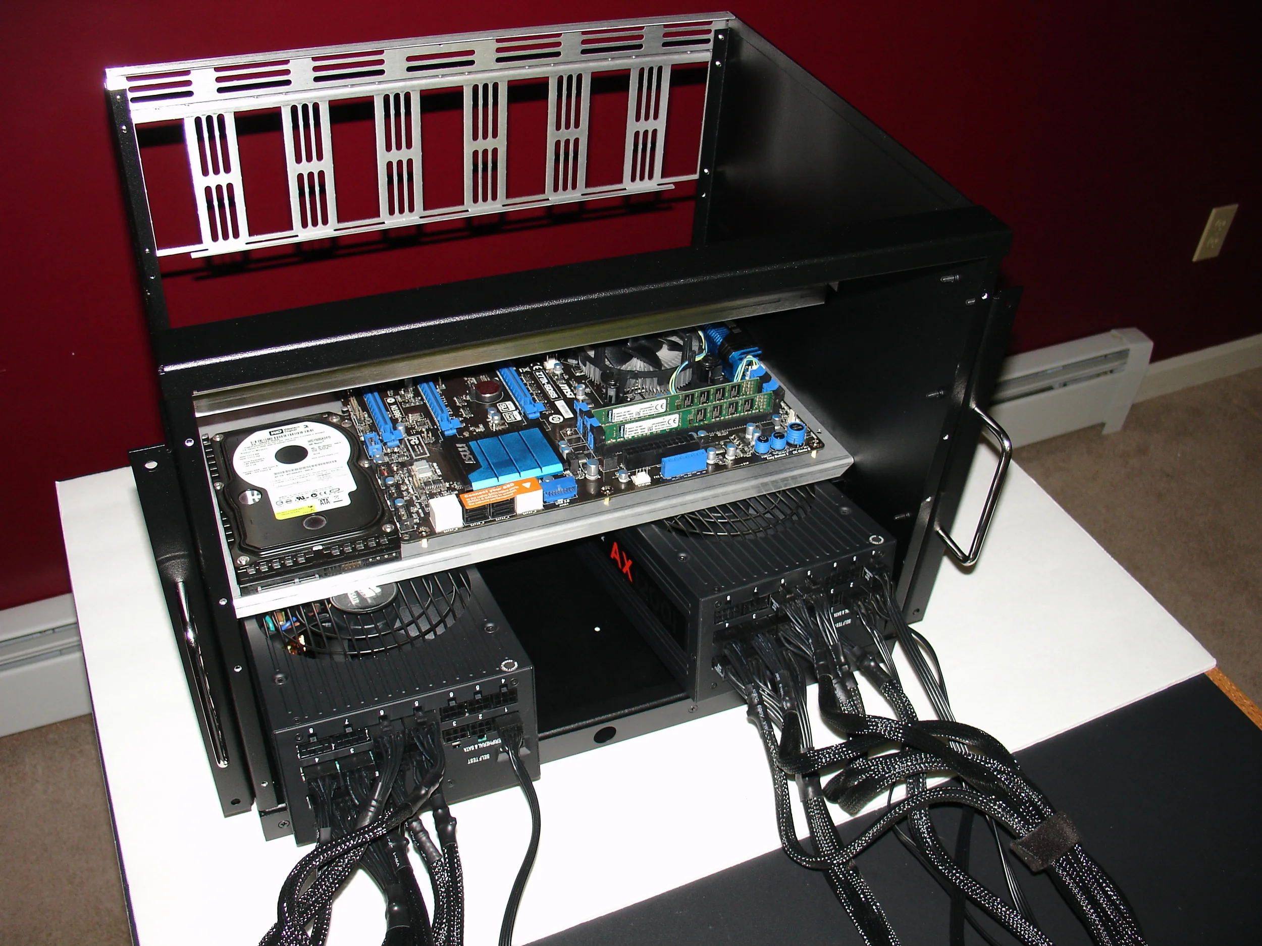
Second ATX Power Supply Installation
The second power supply is installed like the first.

Dual ATX Power Supplies
Both power supplies are installed and will be slid to the back of the chassis for attachment.

Sliding ATX Power Supplies to the Back
The ATX power supplies are slid to the back of the chassis for attachment.

ATX Power Supply Attachment
Both power supplies are attached to the bottom panel using four 6/32 screws each.

Installed Power Supplies
Both power supplies have been installed. Also notice the motherboard back panel has been removed for easy access to the motherboard.

Motherboard Tray Installation
The motherboard tray is held in-place by 4 thumbscrews.

Card Lock-In Bracket Removed
The top card lock-in bracket is removed to enable GPU card installation.

Card Installation
GPU Cards are installed from the outside in with their riser cables attached to the cards. The removal of the motherboard back panel makes this process very quick and easy.

Card Wiring
Cards are installed from the outside in. Powered ribbon cables are layered with their power adapters pulled to the front of the chassis.

7 GPU Cards Fully Installed
7 GPU cards with powered ribbon cables are installed. All power connectors are directed to the front of the chassis. USB risers would simplify this wiring and provide increased airflow. Testing with ribbon cables provides a worst case scenerio for thermal testing.
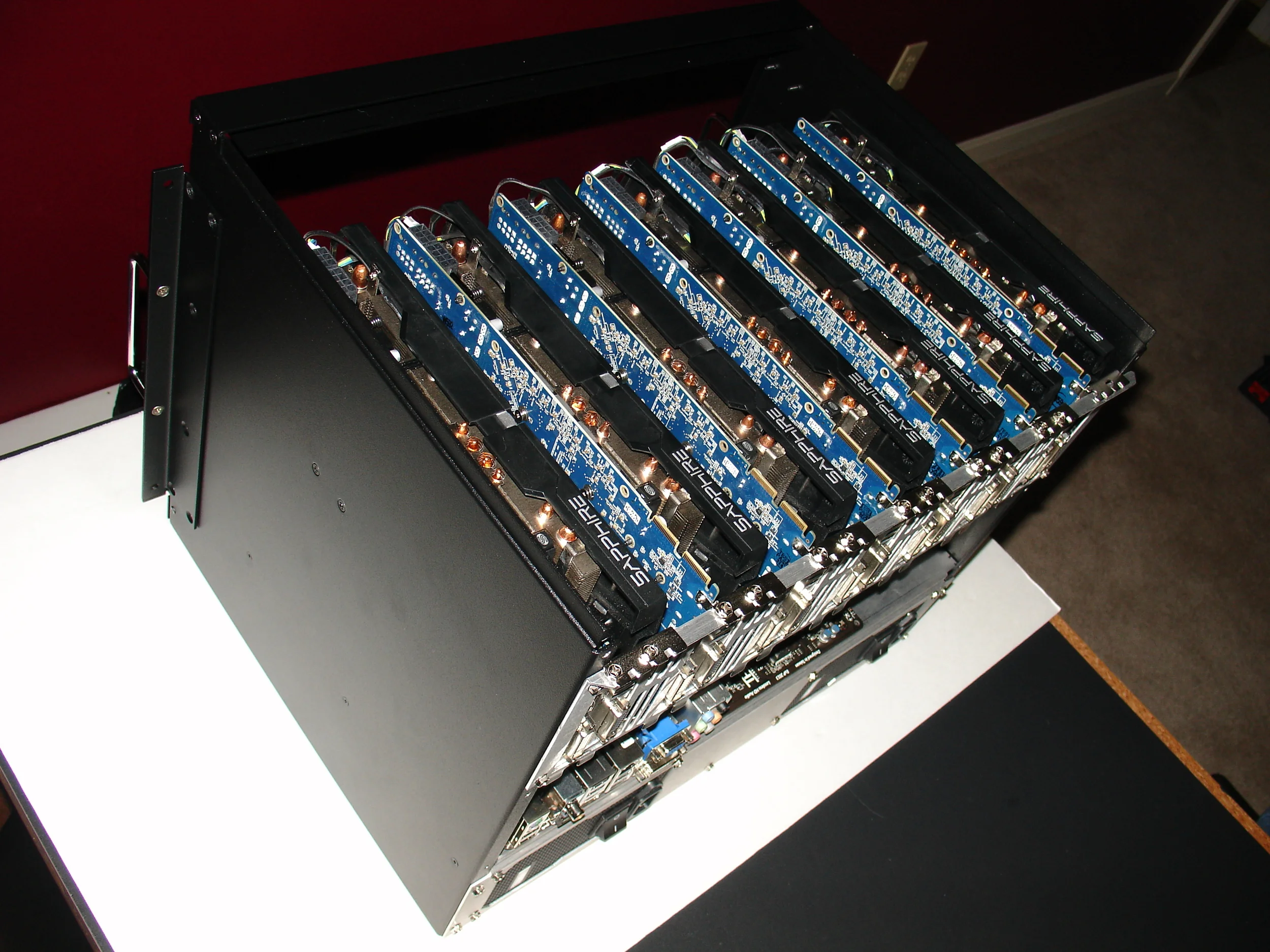
7 GPU Cards, Top View
Gotta love the look of 7 GPU cards in a compact, rack mount chassis :)

Card Lock-On Bracket Installed
Each card had two screws holding it in place. The card lock-on bracket add extra insurance and encloses the top of the chassis.
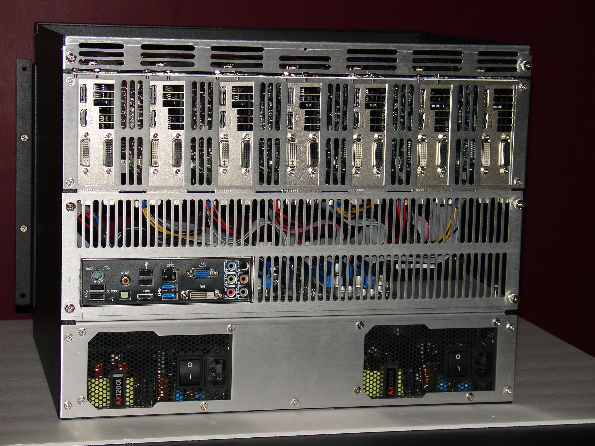
Motherboard Back Panel Installed
The motherboard back panel encloses the mid-section of the chassis. Using this design alternate motherboard and chassis layouts are possible.
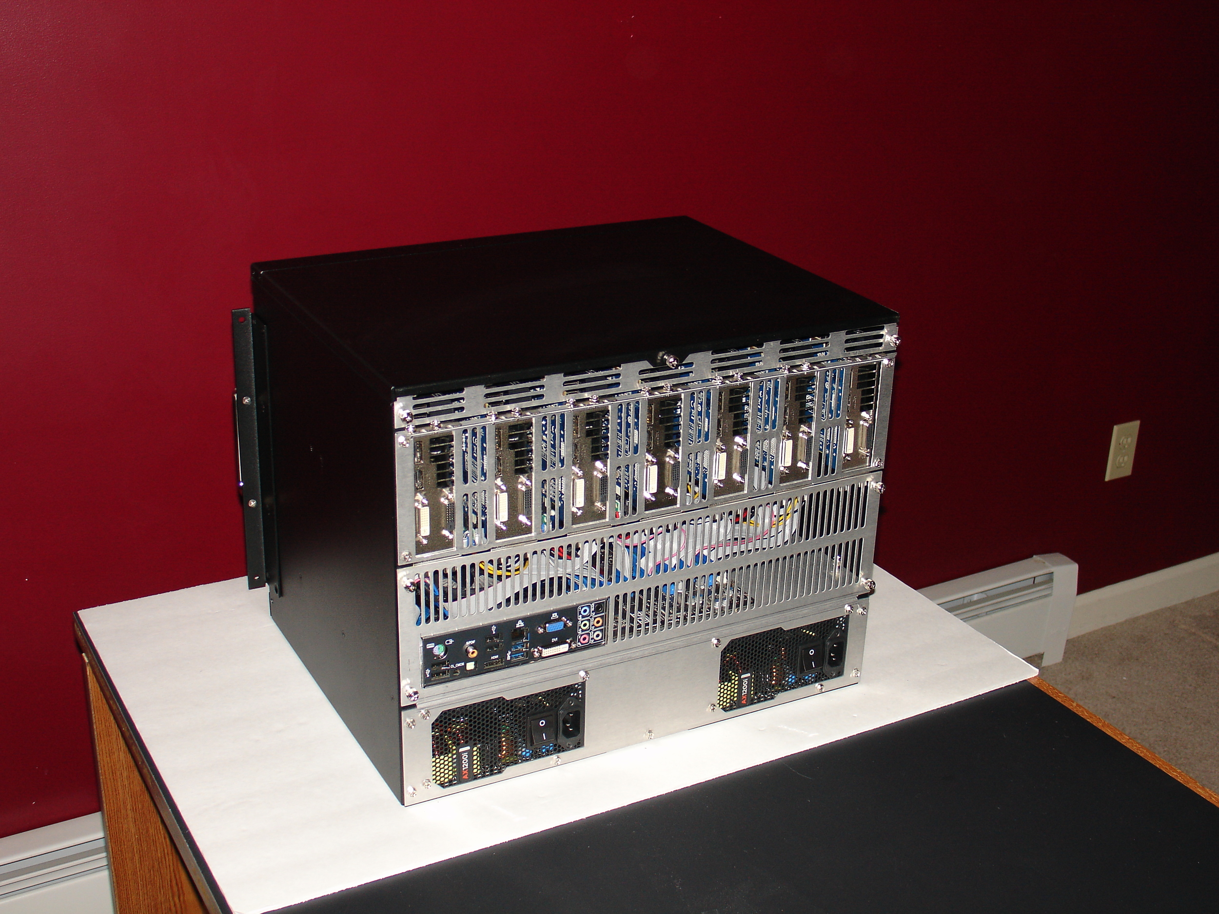
Completed Build from the Back
The chassis top has been added temporarily to show what the completed build will look like.

Attending to those Wires
Now the hard part. There are a ton of wires required for 7 GPUs, and they all have to fit in the chassis without restricting air flow.

Minimizing Wiring Effects on Air Flow
All wires must be moved away from the front panel fan airflow and the card intakes as much as possible. The exact layout will depend on the card and power supply designs you are using. In this layout we have wire wrapped the mass of wires using velcro straps and have pulled them to each side of the chassis. We are also stowing the extra wire at the bottom of the chassis.

Wire Management
The support at the top front of the chassis contains slots for wire management. Each card's power cabling can be attached to this support to increase air flow and reduce stress on the cards and their wiring.

Fan Tray Insertion
An easy way to insert the first fan tray is to place it in the center of the chassis and slide it down. This makes it easy to check the wiring for clearance and adjust as necessary.

Second Fan Tray Installation
The second fan tray is easily installed at the top after the first fan tray is installed in the bottom of the chassis. The empty power button hole in the prototype contains a power button in production. Our prototype build is complete!


